UBC AeroDesign Wiring Hub
Project Images
Learning
- PCB design using Altium.
- Electrical sensor integration and signal protection.
- PCB manufacturing and troubleshooting/testing.
Project Overview
As part of my role on the avionics team at UBC AeroDesign, I designed a wiring hub PCB for centralizing the power distribution, sensor modules, and other peripheral components of the plane. Through this project, I:
- used Altium to design a comprehensive two-layered PCB able to interact with external hardware elements: outlined schematic, component selection.
- assembled a PCB through hand-soldering and conducted hardware troubleshooting tests.
Background
The planes that UBC AeroDesign builds utilizes 10+ different sensors, control surface connections, and other
peripheral components. In the past, power and communication was diverted to these components individually, leading to an extremely cluttered electrical wiring setup. The
wiring hub PCB I designed aims to fix this issue.
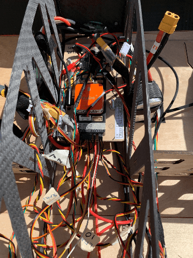
Below is an image of the electrical wiring on the plane before the wiring hub. Very messy!
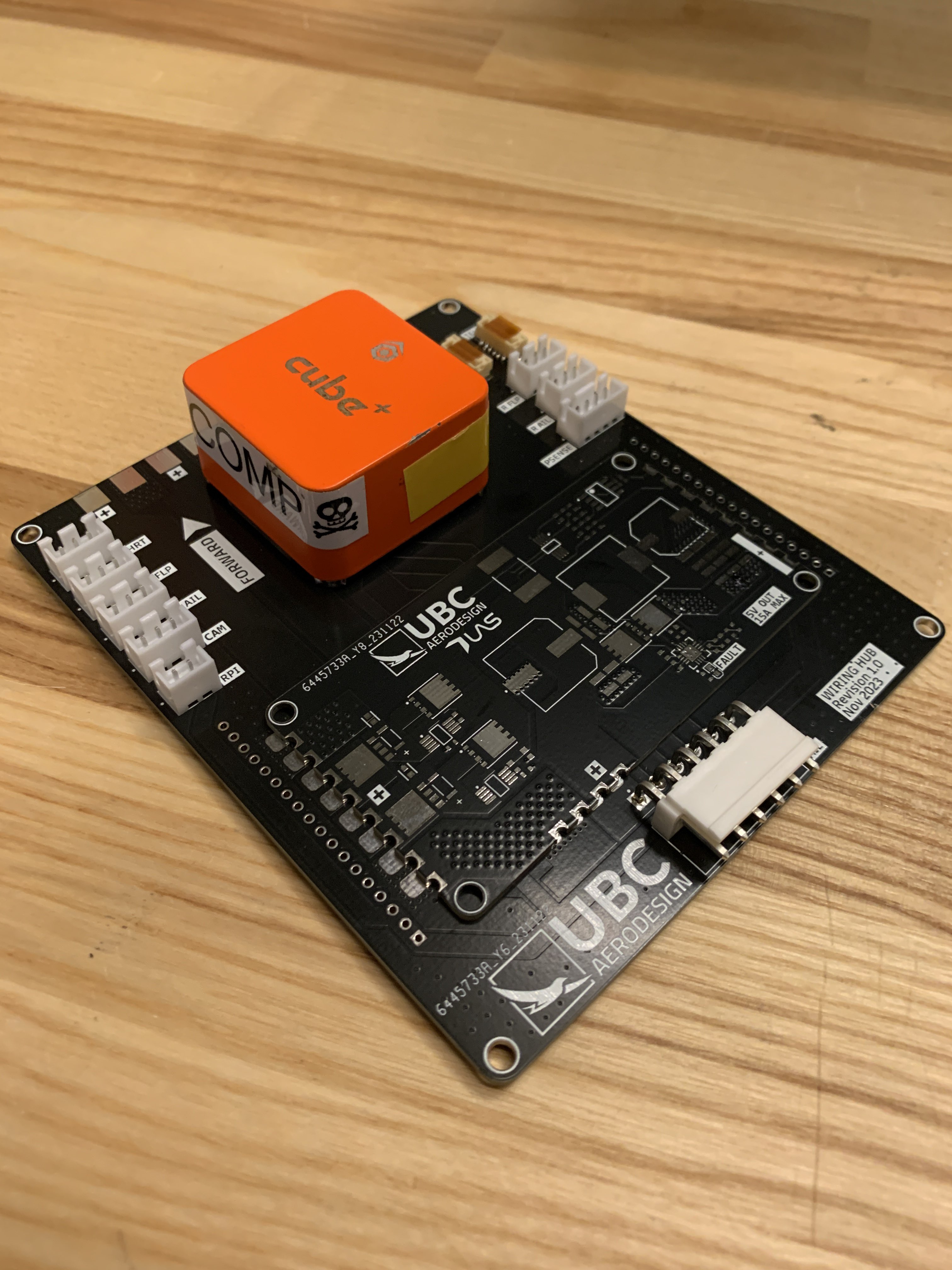
The wiring hub acts as the "motherboard" of the plane. Power and communication to every component on the plane is distributed from this PCB. Moreover, the wiring hub acts as a centralized housing surface for other electrical components. These include the Cube Orange flight controller, a buck converter power distribution board, and a sensor board for communication and sensor functionality.
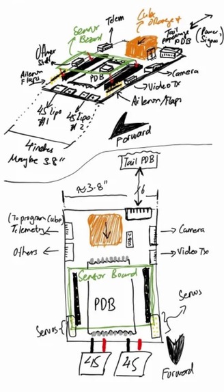
Above is a rough sketch of how the wiring hub was envisioned to look. The Cube Orange is mounted on the wiring hub while the power distribution board is soldered on. The sensor board would be attached on top using pin headers. Moreover, there would be various JST headers for connections to the sensor modules, control surfaces, and other peripherals.
Design and Manufacturing
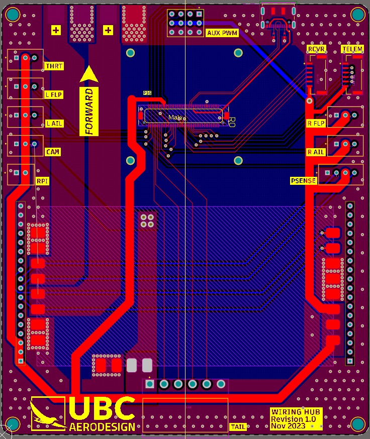

The final wiring hub was designed to be a two-layer board with the necessary pins needed to route communication signals from the Cube Orange to all the components on the plane. Moreover, auxiliary PWM ports were broken out from the Cube Orange in case of the future need for more pins.
USB functionality was implemented for flashing the Cube Orange. However, I did not consider differential signalling or signal protection for this. In a newer revision, I would definitely revist this concept. As the traces were fairly short, the lack of differential routing did not cause a problem. However, this could definitely cause a problem if more EMI-noisy components were used near the wiring hub.
The manufacturing and testing was fairly simple. All connectors were hand-soldered. Flashing, connectivity, and system integration tests were also conducted to ensure that the wiring hub was working as expected.